Troubleshooting I/O Issues in ControlLogix Systems: A Comprehensive Guide
ControlLogix systems—a cornerstone of Rockwell Automation’s Logix5000 platform offer scalable, high-performance control for industrial automation. Yet, like all complex control architectures, I/O issues can arise. These problems may lead to data loss, downtime, or even safety hazards if not quickly identified and addressed.
In the final installment of our ControlLogix blog series, we’ll walk through a practical, step-by-step approach to troubleshooting I/O issues, covering the most common symptoms, causes, diagnostic tools, and real-world examples to help you restore functionality and minimize disruption.
Why I/O Troubleshooting Matters
The Input/Output (I/O) modules in ControlLogix systems serve as the bridge between the PLC and field devices sensors, actuators, drives, and other hardware. If an I/O failure occurs, it can cause:
-
Data loss and control logic interruptions
-
Delays in production and workflow
-
Miscounts, machine faults, or operational safety risks
-
Costly unplanned downtime
Proactive troubleshooting helps identify root causes quickly and ensures consistent, accurate machine performance.
Common I/O Issues in ControlLogix Systems
| Issue | Description |
|---|---|
| Disconnected or damaged cables | Loose or worn wiring causes intermittent or total I/O loss |
| Faulty I/O modules | Hardware defects or aging components may result in module errors |
| Configuration mismatch | Wrong firmware version, slot assignment, or data format |
| Network interruptions | EtherNet/IP or ControlNet failures affecting remote I/O communication |
| Power supply overload | Inadequate voltage leads to I/O faults or inconsistent operation |
Step-by-Step Troubleshooting Guide
Step 1: Check LED Status Indicators
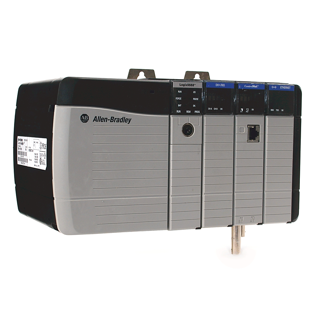
Each ControlLogix I/O module features diagnostic LEDs:
-
OK LED (Green): Indicates module is operating normally
-
Flashing Red: Module fault or communication failure
-
I/O LED Off/Red: No data exchange with controller
-
Network LEDs (on remote I/O): Show link/activity/errors
Tip: Use the LED blink pattern to match against Rockwell’s error codes for faster diagnosis.
Step 2: Use Studio 5000 for Module Diagnostics
Studio 5000 offers real-time insights into I/O health.
-
Module Properties: Check communication status, input/output activity, and fault codes
-
Monitor Tags: Observe input/output tag behavior for signs of inconsistency
-
Controller Logs: Review diagnostic buffer or fault logs to pinpoint failure time and type
Example: An input module shows a red OK LED. Studio 5000 reports “No Data Received.” This likely points to a broken sensor wire or disconnected terminal.
Step 3: Inspect Physical Connections
-
Tighten all terminal blocks
-
Use a multimeter to verify signal continuity and voltage
-
Check connectors on both ends of I/O wiring for corrosion, damage, or misalignment
Real-world example: In a bottling line, a sensor intermittently lost power. Visual inspection revealed a wire was pinched and damaged during panel closure.
Step 4: Verify Configuration in Studio 5000
-
Match slot position to actual hardware
-
Confirm update rates and RPI settings are appropriate
-
Ensure firmware compatibility between the I/O module and processor
-
Watch for mismatched data types (e.g., INT vs. DINT) in Add-On Instructions
If you recently replaced a module, confirm that the part number and configuration match what’s defined in the program.
Step 5: Check Power Supply Health
-
Use a multimeter to confirm voltage output
-
Compare total current load vs. rated capacity
-
Distribute high-load I/O modules across multiple supplies if needed
Under-voltage conditions may cause modules to "drop off" or reset unexpectedly.
Step 6: Inspect Network Communication (For Remote I/O)
-
Confirm proper IP address assignment and subnet configuration
-
Use Rockwell’s BootP or FactoryTalk Linx tools for diagnostics
-
Use Wireshark or managed switch tools to detect high traffic or collisions
-
Replace suspect network cables or switch ports
Example: An EtherNet/IP drop between a ControlLogix chassis and remote I/O rack caused sporadic tag delays. Swapping a damaged patch cable restored consistent communication.
Real-World Case Study: Pharmaceutical Line Malfunction
Scenario: A pharmaceutical line's fill-count tracking fails containers are inconsistently filled.
Symptoms:
-
Operator panel shows erratic product count
-
A discrete input I/O module’s OK LED is flashing red
Actions Taken:
-
Checked Studio 5000: Module properties flagged "No Input Data"
-
Inspected sensor wiring: Found a frayed cable
-
Replaced cable: Restored I/O signal
-
Monitored Tags: Accurate counts resumed within minutes
Outcome: The issue was resolved in under 30 minutes, saving a full shift of lost product.
Final Takeaway
ControlLogix I/O issues are often caused by simple faults—loose wires, incorrect configuration, or power/network problems. The key is to follow a systematic, structured process:
-
LED indicators →
-
Studio 5000 diagnostics →
-
Physical inspection →
-
Software configuration →
-
Power/network checks
By mastering these steps, technicians can quickly identify the source of I/O faults, reduce downtime, and maintain safe, high-performance operations.
For more information, contact PLG Automation:
Email: sales@plgautomation.com
Phone: 800-906-9271