Troubleshooting Tutorial: Common SLC 500 Faults – Part 1
Introduction Programmable Logic Controllers (PLC) such as Allen-Bradley’s SLC 500 Modular or Fixed style hardware are designed with self-diagnostic capabilities. With self-diagnostics, the controller can detect the operational status of every module and report this externally through the behavior of built-in LED indicators and internally via the diagnostic buffer.
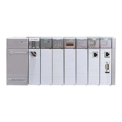
II. SLC 500 LED Indicators An SLC 500 controller is provided with LED indicators such as:
-
RUN (All controllers)
-
CPU FAULT (SLC 5/01 and SLC 5/02)
-
FLT (SLC 5/03; SLC 5/04; SLC 5/05)
-
BATTERY LOW (SLC 5/01 and SLC 5/02)
-
BATT (SLC 5/03; SLC 5/04; SLC 5/05)
-
FORCED I/O (SLC 5/01 and SLC 5/02)
-
FORCE (SLC 5/03; SLC 5/04; SLC 5/05)
-
RS232 (SLC 5/03; SLC 5/04; SLC 5/05)
-
DH485 (SLC 5/03)
-
DH+ (SLC 5/04)
-
ETHERNET (SLC 5/05)
Generally, faults are made known when the CPU FAULT or FLT LED is energized RED. Other controller states such as battery status, I/O status, communication, and controller modes are also indicated by the state of individual LEDs.
When the FAULT LED is activated, it prompts the user to take action. Identifying the fault message before attempting to remove the error is critical. Without identifying and addressing the root cause, the fault is likely to return.
III. Fault Handling There are several methods to remove faults from a faulted controller:
A. Hardware Corrections:
-
Switching controller mode from RUN to STOP and back to RUN
-
Power cycling the controller or the entire SLC 500 rack
B. Software Corrections:
-
Downloading the entire program
-
Clearing the fault
-
Identifying the fault via error codes listed in the diagnostic buffer and applying the appropriate correction
Among these methods, the most effective approach is using the diagnostic buffer to identify error codes. This enables precise correction, minimizing the chance of repeated faults.
IV. Accessing the Diagnostic Buffer The diagnostic buffer is the Data File S2. It is accessible by:
A. Going ONLINE with the controller. Note: The Data File S2 must be accessed ONLINE. When viewed OFFLINE, the processor may appear fault-free or show outdated information.
To access the data file of a FAULTED controller:
-
Navigate through the controller panel in the upper left of RSLogix 500 software.
-
Click the drop-down arrow and select “Goto Error”. This directs the user to the “Errors” tab.
B. Directly Through the Data Files:
-
Open the Data File S2 to access the diagnostic buffer.
When an error is present, a phrase or paragraph describing the error will appear in the error description box, along with an error code in HEX format. Both pieces of information are vital in determining corrective actions.
V. Tools and Skills Needed to Troubleshoot an SLC 500 Fault A systematic approach is necessary to determine the root cause of faults and prevent recurring errors. Required tools and knowledge include:
-
Programming workstation with RSLogix 500 software installed
-
Communication cable for connecting to the controller
-
SLC 500 Instruction Set Reference Manual (includes fault codes and resolutions)
-
Familiarity with downloading and uploading user programs (refer to the appendix for procedure)
VI. Common SLC 500 Faults With a solid understanding of fault identification and diagnostics, it is helpful to review common SLC 500 faults and their corrective actions. This knowledge improves controller availability and helps prevent unplanned shutdowns.
In the next sections, we will cover common SLC 500 Processor Faults and I/O Hardware Faults.
Contact PLG Automation
Email: sales@plgautomation.com
Phone: 800-906-9271