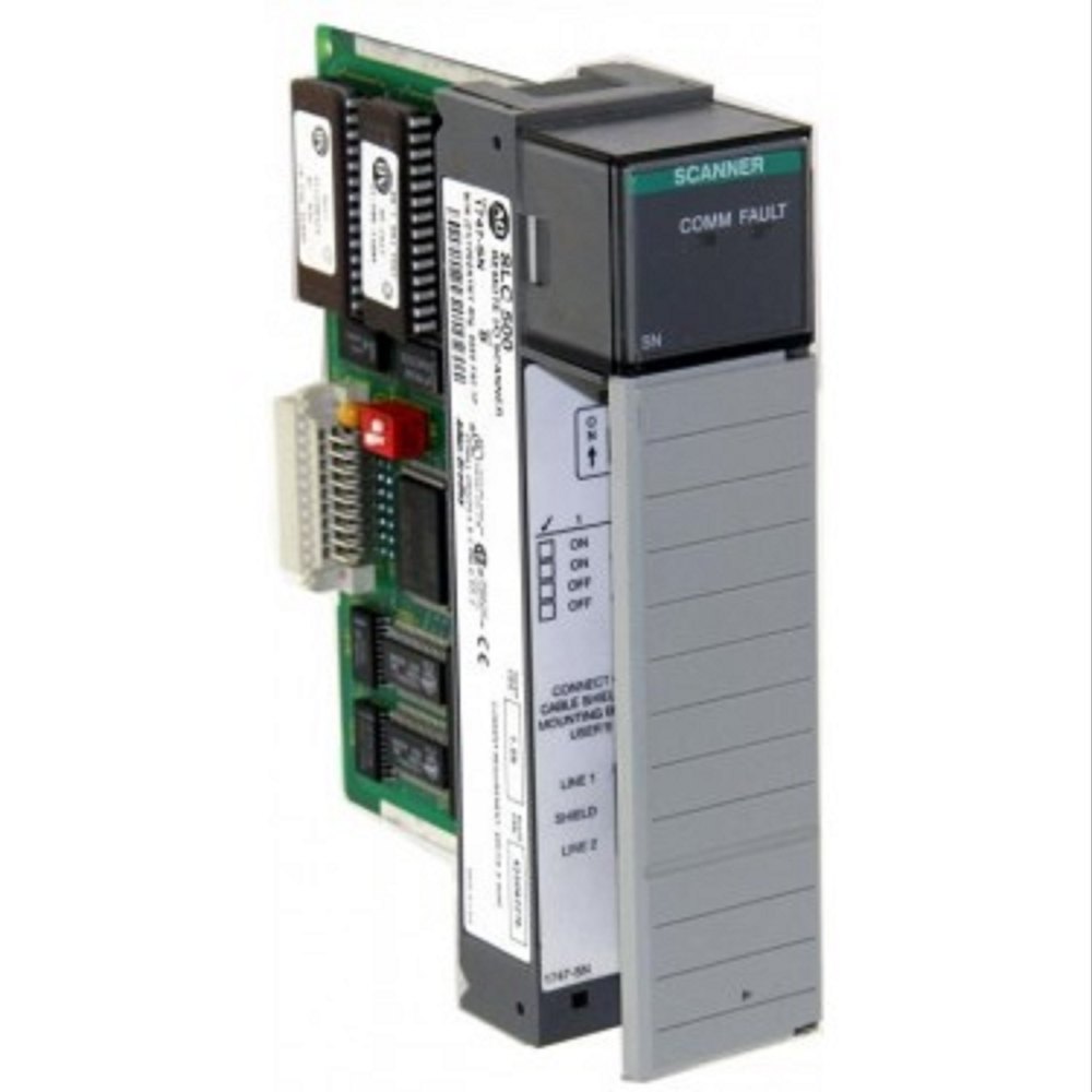
SLC 500 Power Supplies
The SLC 500 modular control system from Allen-Bradley includes essential components such as power supplies, CPUs, input/output modules, and operator interface devices. These modular controllers can support up to three I/O modules and are widely used in industrial automation environments requiring programmable logic controllers (PLCs), distributed I/O systems, actuators, and sensors.
Environment and Enclosure
SLC 500 power supplies are intended for Pollution Degree 2 industrial settings with Overvoltage Category II (IEC 60664-1). They are rated Class A, Group 1 for industrial-grade operation at altitudes up to 2,000 meters (6,561 feet). While the open-type design requires user-supplied housing, proper environmental precautions must be taken to ensure performance and EMC compliance.
Hazardous Location Considerations
Each unit is labeled with a hazardous location temperature code. For safe use:
-
Disconnect all power before servicing.
-
Avoid connecting/disconnecting under live conditions.
-
Use manufacturer-supplied connectors.
-
Do not substitute components in hazardous locations without verifying compliance.
Selecting SLC 500 Power Supply
To select an SLC 500 power supply, consult:
-
Power supply specifications.
-
The correct worksheet for your model.
-
Publication 1747-SG001 (SLC 500 Systems Selection Guide).
Each chassis requires one power supply. Overloading a power supply may result in system failure.
Use of Isolation Transformer
In environments with high electromagnetic interference (EMI), an isolation transformer is recommended. This device stabilizes voltage and prevents noise from affecting control operations. To size the transformer:
-
Sum the power demand of all connected loads.
-
Determine the required VA rating based on I/O pin counts and expected current draw.
Input Voltage Characteristics
Acceptable input voltage ranges:
-
85-132V AC RMS (for 120V operation).
-
170-265V AC RMS (for 240V operation).
-
Frequency: 47 to 63 Hz.
Operating Range and Hold-Up Time
SLC 500 systems typically allow 20ms to 3s of operation following a power interruption, depending on the configuration. After that, power-down sequences begin, disabling status indicators and logging a remote power failure in multi-chassis systems.
Power Down Input States
Because input modules may still register state changes during a brief power loss, programs must account for these transitions. Reserve an input to monitor whether inputs remain ON to ensure accurate logic execution during power events.
24V DC Overcurrent Condition
Specific models behave differently during 24V DC overcurrent events. For example:
-
1746-P1 (Japan), 1746-P2 (Series A, B), and 1746-P4 (Series A) should restart the user program.
-
1746-P1 (Malaysia), 1746-P2 (Series C), 1746-P5/P6 (Series A) auto-correct the fault and continue CPU operation.
Undervoltage Operation
Controllers will shut down below voltage thresholds and resume when restored. Notably, 1746-P7 shuts down below 4-9V and will not restart until voltage stabilizes.
General Specifications
1746-P1
-
Voltage: 85-132/170-265V AC @ 47-63 Hz
-
Power: 135VA
-
Inrush: 20A
-
Output: 2A @ 5V DC, 0.46A @ 24V DC (200mA user power)
-
Isolation: 1800V AC RMS
-
Hold-up: 20ms (full load), 3000ms (no load)
1746-P2
-
Voltage: 85-132/170-265V AC
-
Power: 180VA
-
Output: 5A @ 5V, 0.96A @ 24V (200mA user power)
1746-P3
-
Voltage: 19.2-28.8V DC
-
Power: 90VA
-
Output: 3.6A @ 5V, 0.87A @ 24V
-
Hold-up: 5ms (full), 1000ms (no load)
1746-P4
-
Voltage: 85-132/170-250V AC
-
Power: 150VA
-
Inrush: 45A
-
Output: 10A @ 5V, 2.88A @ 24V
-
Isolation: 2600V DC
1746-P5
-
Voltage: 90-146V DC
-
Power: 75VA
-
Output: 5A @ 5V, 0.96A @ 24V
1746-P6
-
Voltage: 30-60V DC
-
Power: 100VA
-
Output: 5A @ 5V, 0.96A @ 24V
1746-P7
-
Voltage: 10-30V DC
-
Output: Up to 3.6A @ 5V, 0.87A @ 24V
-
Detailed hold-up: up to 1860ms depending on voltage level and load
Sinking and Sourcing Points for I/P Modules
-
Sourcing: Field device provides current.
-
Sinking: Field device receives current.
These principles apply across input/output configurations and must be matched accordingly to avoid faults.
Solid-State DC I/O Circuits
-
Sourcing input with sinking field device: Field device connects on negative side.
-
Sinking input with sourcing field device: Field device connects on positive side.
-
Sourcing output to sinking device: Power supplied to field device.
-
Sinking output to sourcing device: Field device sinks current from output.
Powering the Link Coupler
In normal setups, the controller powers the link coupler. If not connected, use an external 24V DC power supply. Current requirements:
-
85mA (no peripherals)
-
190mA (with peripherals)
Use the 1747-C11 cable for processor-to-coupler connection.
Conclusion
The Allen-Bradley SLC 500 power supply family supports a wide range of industrial applications. Proper selection, installation, and understanding of module compatibility, wiring practices, and environmental ratings ensure reliable system performance and longevity.
Contact PLG Automation for expert guidance on selecting and sourcing the right Allen-Bradley ControlLogix power supply for your application.
Contact Us:
📧 sales@plgautomation.com
📞 800-906-9271
